Description
A flow transmitter is a vital component in many industrial processes where accurate monitoring and control of fluid flow is essential. It is an instrument designed to measure the flow rate of a fluid, typically liquid or gas, and convert this measurement into an electrical signal that can be interpreted by control systems or displayed on monitoring devices.
Here’s an overview of how a flow transmitter works and its key components:
- Primary Sensing Element: The primary sensing element of a flow transmitter is responsible for directly measuring the flow of the fluid. There are various types of primary sensing elements, including orifice plates, venturi tubes, flow nozzles, magnetic flow meters, turbine flow meters, ultrasonic flow meters, and others. Each type has its own principles of operation and is selected based on factors such as the type of fluid, flow rate range, pressure, temperature, and accuracy requirements.
- Signal Conditioning: Once the primary sensing element measures the flow, the raw data needs to be conditioned and converted into a usable electrical signal. This process involves amplifying, filtering, linearizing, and compensating for factors such as temperature and pressure variations. The goal is to ensure that the output signal accurately represents the flow rate of the fluid.
- Output Signal: The output signal of a flow transmitter is typically in the form of a standardized electrical signal, such as a voltage, current, or frequency, which corresponds to the flow rate being measured. Common output signals include 4-20 mA, 0-5 VDC, 0-10 VDC, and digital communication protocols like HART (Highway Addressable Remote Transducer) or Modbus.
- Transmitter Electronics: The transmitter electronics consist of circuitry and components that process the conditioned signal and generate the output signal. This may include microprocessors, analog-to-digital converters (ADC), digital signal processors (DSP), memory, and communication interfaces.
- Housing and Enclosure: Flow transmitters are typically housed in rugged enclosures designed to withstand the operating conditions of industrial environments. These enclosures provide protection against factors such as moisture, dust, vibration, and temperature extremes.
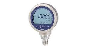
- Display and User Interface: Some flow transmitters include a built-in display and user interface for local monitoring and configuration. The display may show parameters such as flow rate, totalized flow, diagnostic information, and configuration settings. User interfaces may include buttons, switches, or touchscreens for navigation and input.
Flow transmitters are used in a wide range of industries, including oil and gas, chemical processing, water and wastewater treatment, power generation, pharmaceuticals, and food and beverage production. They play a crucial role in ensuring the efficiency, safety, and reliability of industrial processes by providing accurate flow measurements for process control, monitoring, and optimization.